In this post I will be taking a look inside the ZAP 3L remote switch outlets and their remote control, roughly describe the circuits involved and look at how the communication protocol works. The tech involved is pretty simple (mains-powered radio receiver & decoder) yet I learned plenty about power supply design, safety, and radios 🙂 These plugs seem to still be popular on Amazon despite the proliferation of “smart” plugs with wifi and google/siri/alexa support. Let’s dive in!
The devices
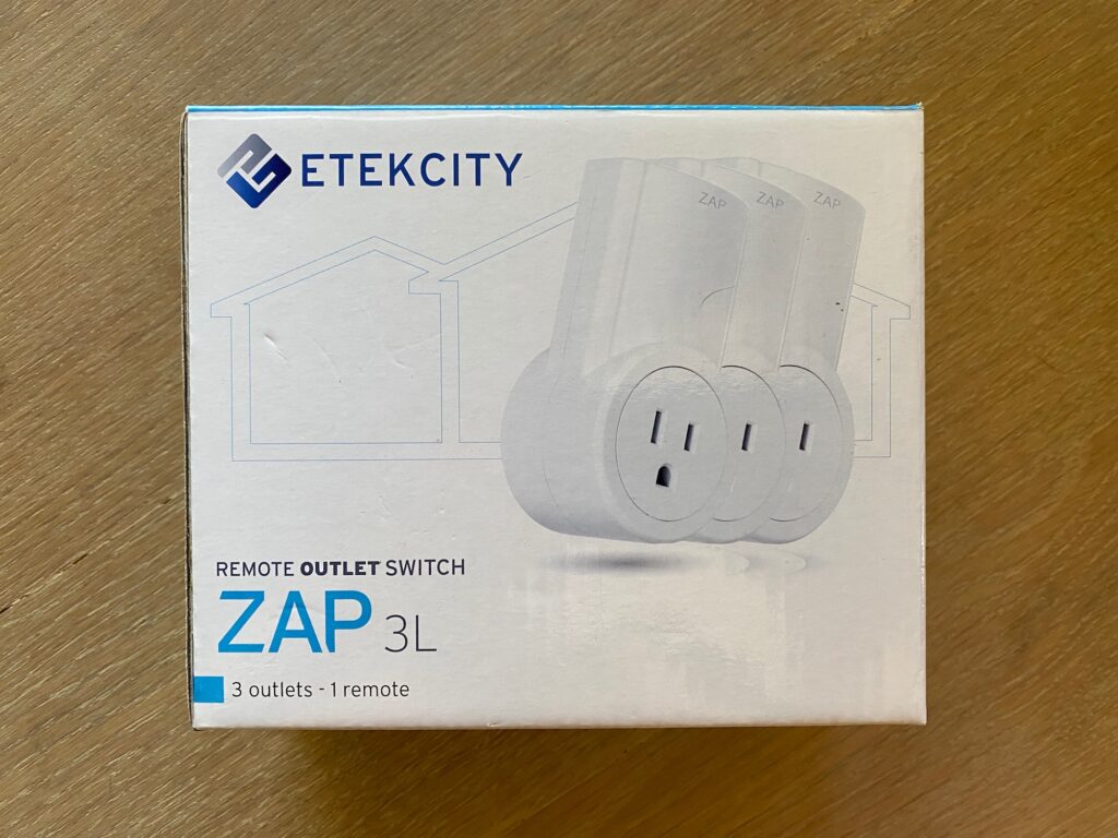
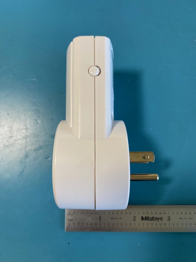
These are Etekcity’s ZAP 3L Remote Outlet Switch: a simple remote-control outlet with an on/off remote, operating via radio over the common 433.92MHz frequency (car key fobs, garage door openers, etc). You press ON and the outlet turns on, press OFF and it turns off; pretty straightforward operation!
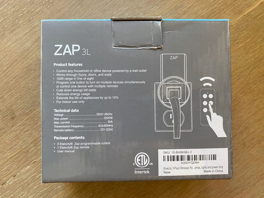
Basic listed specs:
- 120V AC / 60Hz
- 10A max load (1200W max)
- Frequency: 433.92Mhz
- 100ft range in line of sight
The model number at the back of the switch is 10-BH9938U. A quick search and we can see what the FCC knows about these devices: FCC ID Q92-BH9938U for the outlet and FCC ID Q92-BHOP for the remote (although the remote at the FCC doesn’t use the same HS2260A chip). The FCC application was submitted by NINGBO BAIHUANG ELECTRIC APPLIANCES CO., a company based in China. It’s fair to say that “Etekcity” works better for the US market.
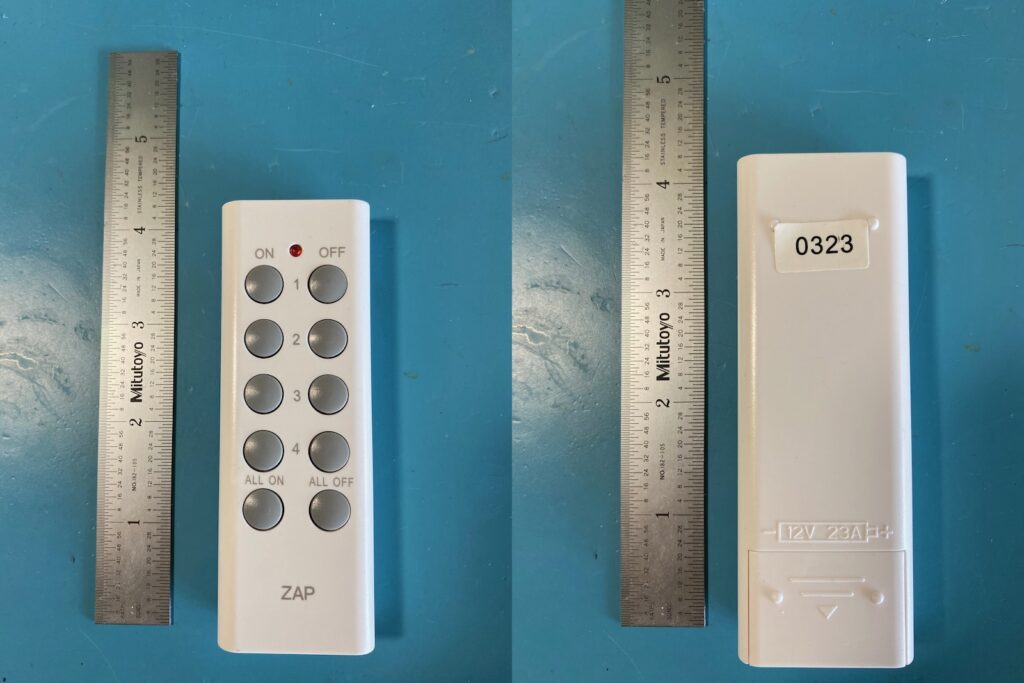
No fanfare here. My package came with three outlets and one remote as pictured below
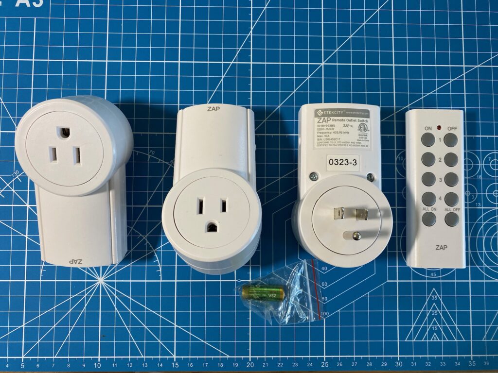
The plug has a button on the side to be able to turn it on or off manually, and to learn a specific code from a remote or to reset the programming completely.
Teardown: plug
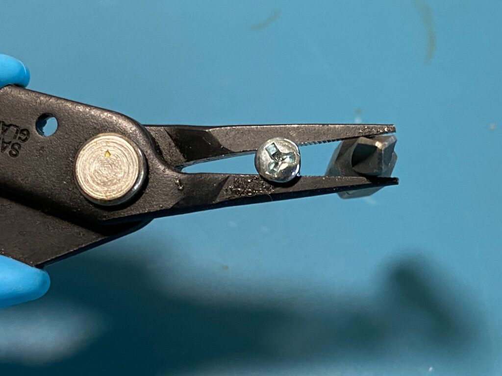
The journey begins by removing the two screws at the back. The situation is made slightly more complicated by the use of three-prong safety screws, as required by the design of the power supply which we’ll talk about later on. With the right tool though it’s no different than a normal screw.
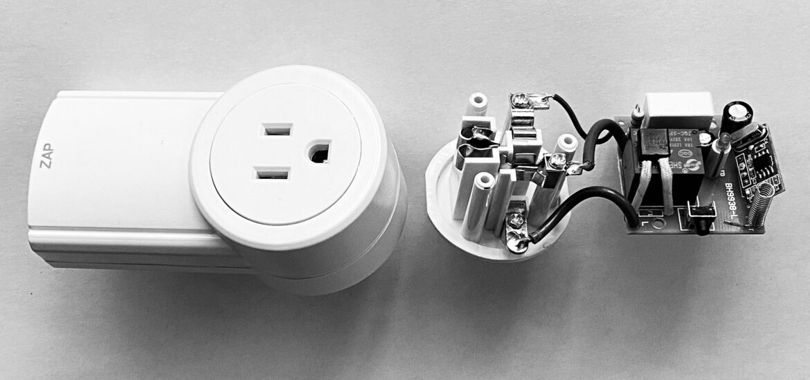
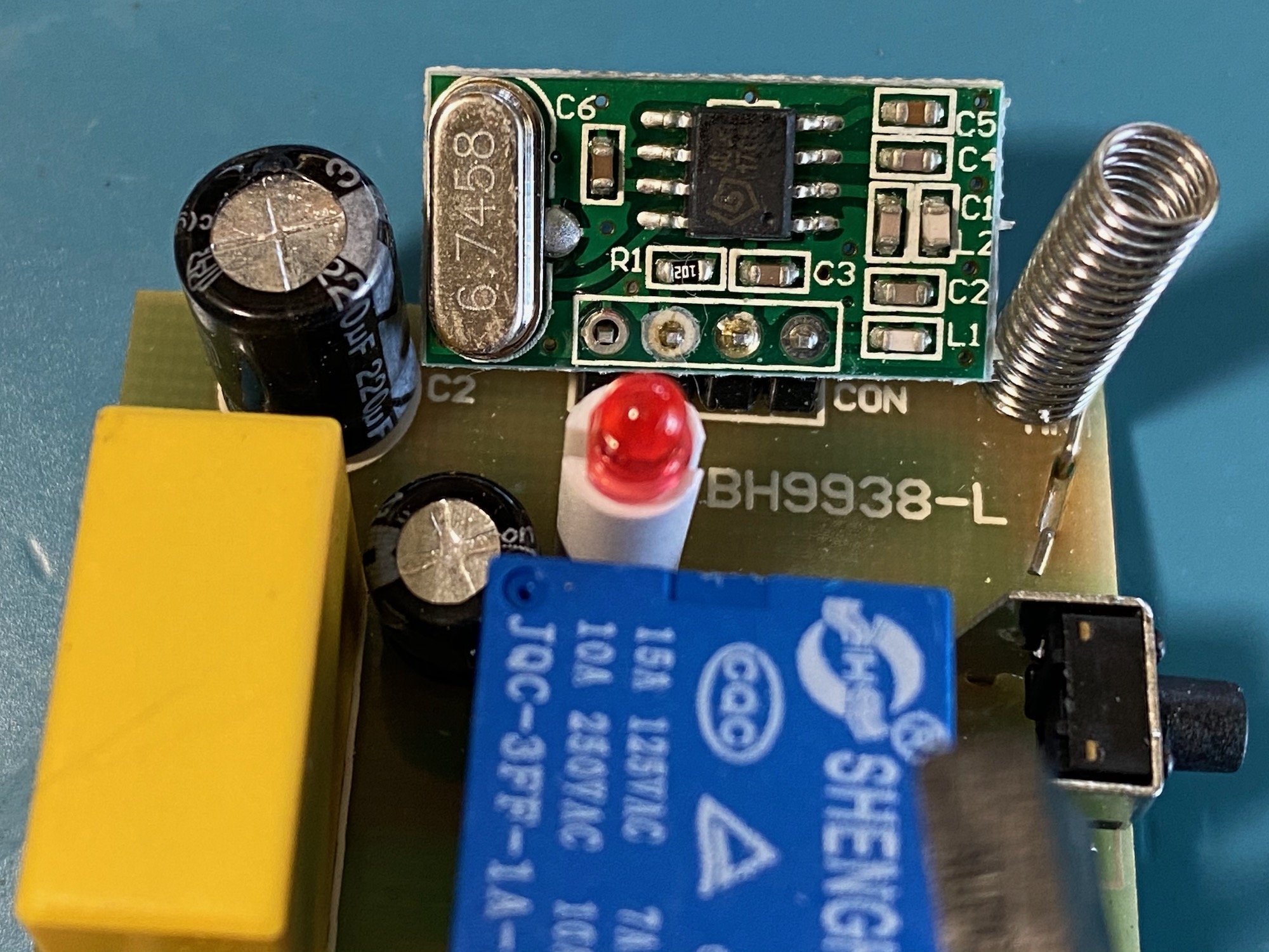
Once open we see a seemingly very simple design: a small circuit with just a few components and a couple of wires to connect it to the outlet’s prongs.
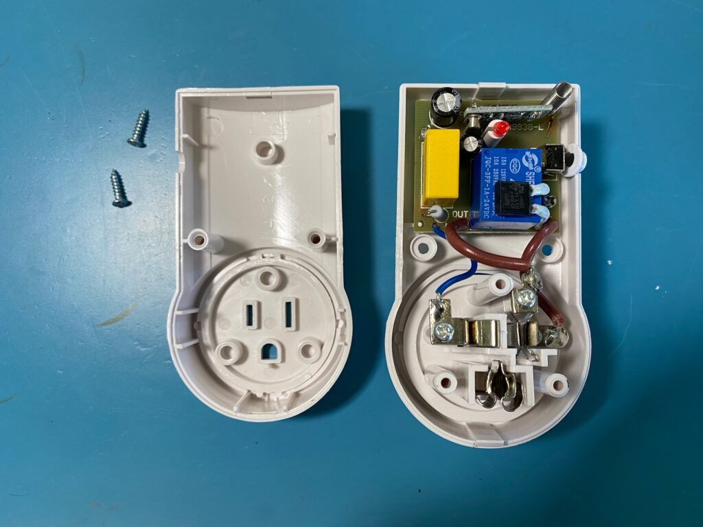
The circuit’s PCB is held to the case by two little Philipps screws (you can see them in the photo above right above the yellow capacitor, and on the right of the blue relay). After removing these two screws the circuit and the prongs pop right out of the enclosure and we can start taking a closer look at how it works. The outlet lets the Ground and Neutral prongs go straight through, and switches the Live (Hot) prong with a standard 10A relay.
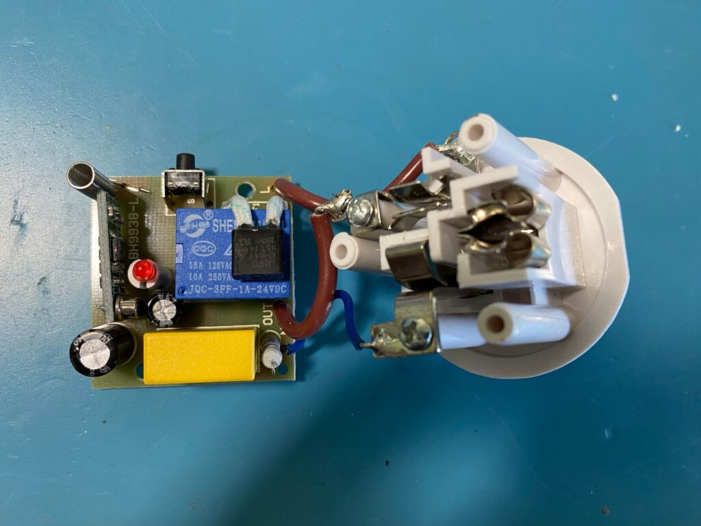
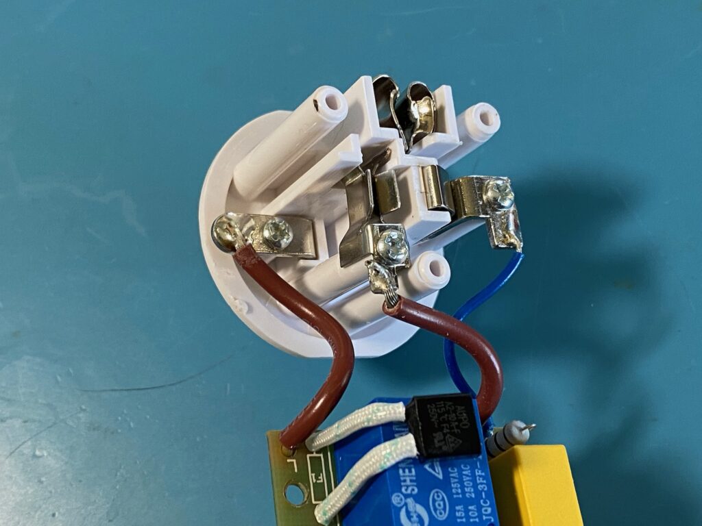
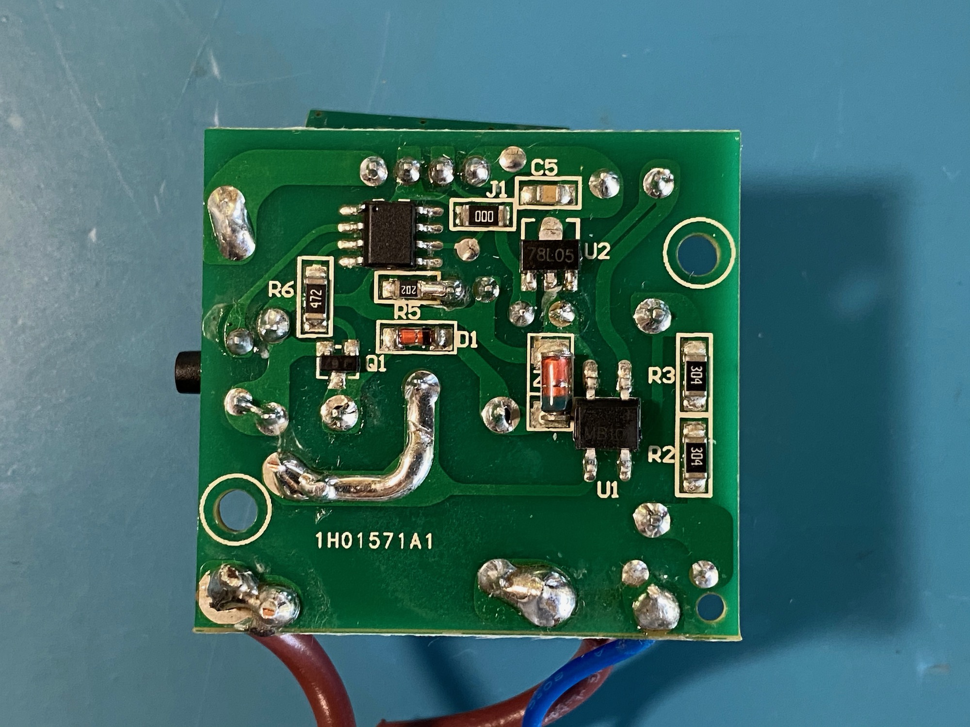
The circuit is on a single-sided PCB with a few big through-hole components on top, and a few surface-mount components on the bottom (which is the copper-side of the PCB). One of the “components” is another tiny PCB labeled “RX-480R” mounted at a right-angle with simple 0.1″ headers. Like we’ll see a bit later the little PCB is the radio receiver for the module.
Outlet PCB: look ma, no transformer! Circuit Analysis
This is where things get interesting. At first glance the circuit seems like nothing special but looking deeper I realized all the usual power supply suspects where nowhere to be found. No transformer? No switching controller? How does this thing pull some low-voltage DC from the mains?
The answer: A Transformerless Power Supply (TPS), something apparently reasonably common in those tiny mains-powered devices. I found two resources that were really helpful in understanding the theory:
- This great article on Hackaday which gives a really good overview and puts a good emphasis on the safety aspect of such a thing: The Shocking Truth About Transformerless Power Supplies
- A detailed design note from Designer Circuits: Transformerless Power Supply Design (pdf) which digs a bit more into the theory of TPS
The main takeaway here is that it is possible to design very cheap, tiny, and reasonably efficient mains-powered power supplies without using a transformer. But without a transformer none of the circuit is isolated from the mains and it can be extremely dangerous to work with, a hiccup anywhere and it will fry your equipment and kill you in your lab. These designs are only suitable when the device is going to be completely enclosed and isolated with no means of touching or connecting to the insides (like this outlet, or a smart lightbulb, etc). That’s why they put those safety screws on the device: don’t poke inside!
Back to our circuit. Now that we have a sense of how the power situation might work, let’s dive into the specifics, including a reverse-engineered schematics.
The components on the main PCB are:
- Relay: Shenghaiwai JQC-3FF-1A-24VDC: The relay doing the hard work switching the 120V circuit on/off. (Here’s some info about a similar but not quite the same relay: datasheet PDF). The nominal voltage for the solenoid is 24VDC and the relay can in theory pass 10A@250VAC or 15A@125VAC
- R1: in-rush limiting resistor, 46Ohms 5%
- C1: mains series capacitor, X2 rated: MKP-X2, 0.68uF 305V. Info for a similar capacitor: datasheet PDF
- F1: mains fuse, Thermal Cut-Off (TCO) Aupo A2-10A-F, 115F
- C2: 220uF 35V Electrolytic
- C3: 220uF 10V Electrolytic
- R2, R3: 300K SMD
- R5: 2K SMD
- R6: 4K7 SMD
- ZD1: 24V Zener Diode
- Q1: NPN Transistor in a SOT-23 package, markings “J6”, a S9014 (pdf) maybe? It drives the solenoid of the relay
- U1: Full-bridge rectifier with “MB10S” markings similar to the ON Semi MB10S (pdf)
- U2: 78L05 LDO 5V voltage regulator (similar to ST’s 78L series, pdf)
- U3: The unknown MCU driving the switch. 5V power on Pin 1, GND on Pin 8
Markings on the main PCB:
- Top: BH9938-L
- Bottom: 1H01571A1
With that out of the way let’s look at the schematics I recreated by tracing the circuit (which means, it might be incorrect in more than one way):
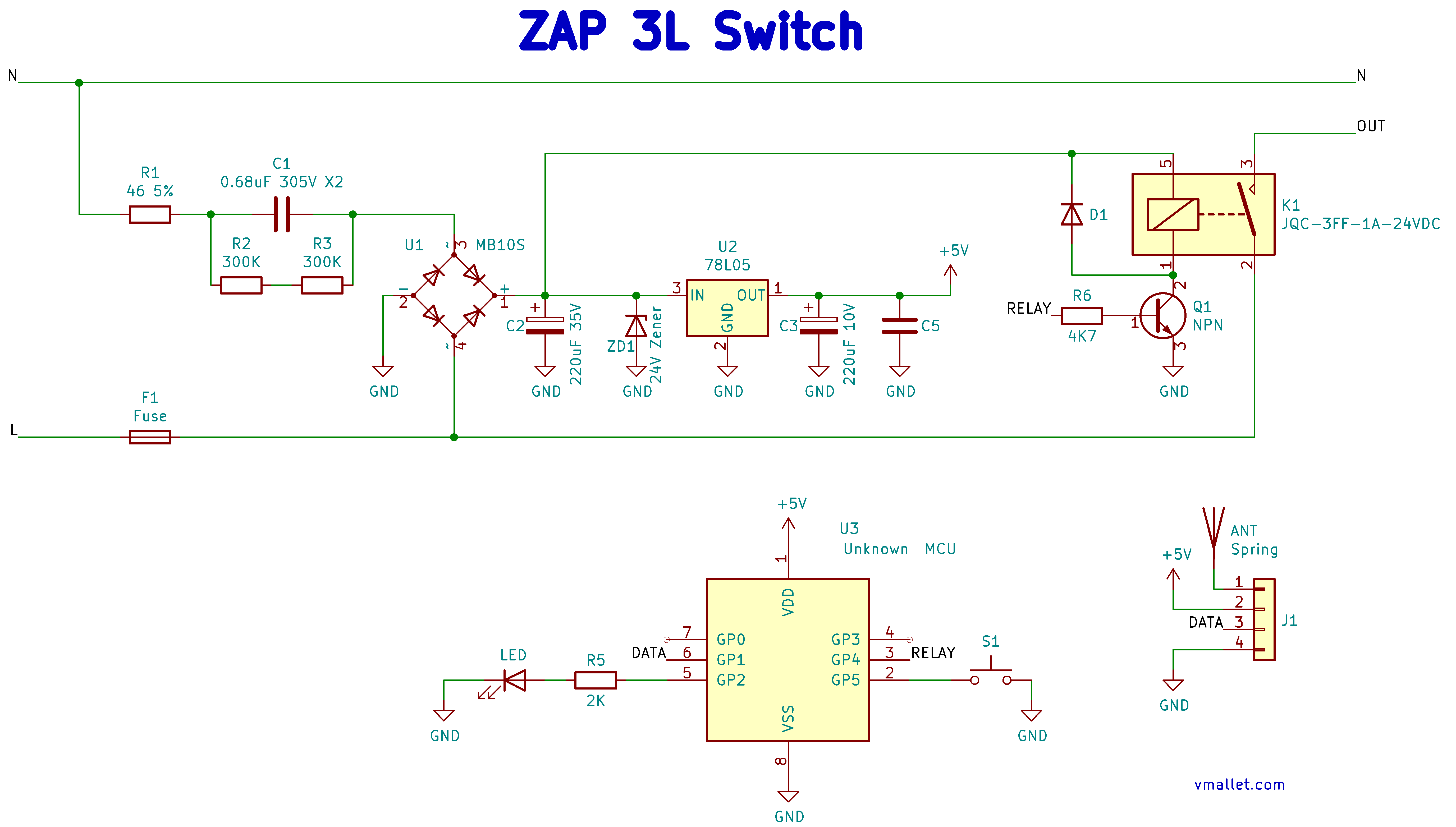
C1, U1, C2, and ZD1 are what makes up the basis of the transformerless power supply, providing about 24V DC to the system. R1 limits the in-rush current going into C1 when we plug it in to avoid tripping the (most-likely) 15A breaker on the circuit and reducing the chances of seeing nice sparks too. R2 and R3 in series form a 600K bleeder resistor to drain C1 once unplugged, so C1 doesn’t stay charged with a high voltage once disconnected.
The 24V DC power serves two purposes: it is used to energize the relay’s coil (driven by Q1), and it is fed into the U2 voltage regulator that produces a more predictable 5V supply for the rest of the system. The MCU and the radio receiver both run on 5V.
The unknown MCU has 6 pins that might be GPIOs. One is for driving the LED on/off, one is for receiving data from the radio receiver, one is for driving the base of Q1 (to then drive the relay), and one is to read the push-button switch. Two pins remain unconnected.
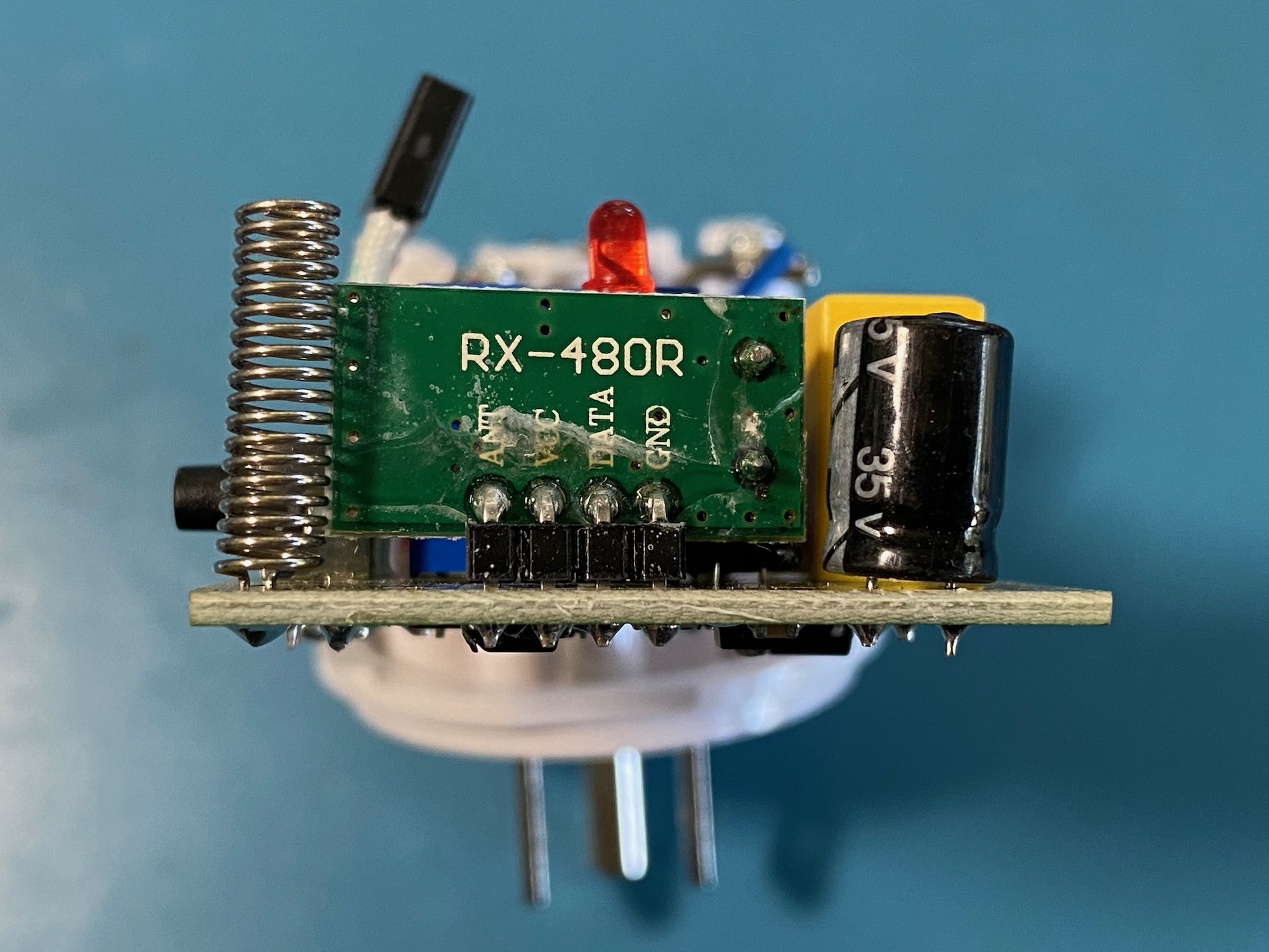
The radio receiver is quite straightforward too, with one chip taking care of pretty much everything:
The main chip on the RX-480R receiver PCB is a Synoxo SYN480R 300-450Mhz ASK Receiver (pdf) configured with the 6.7458Mhz crystal and a few passives to run at 433.92Mhz. It has a 4-pin header: GND, DATA, VCC (5V), and ANTenna.
The reverse-engineered schematics looks like this:
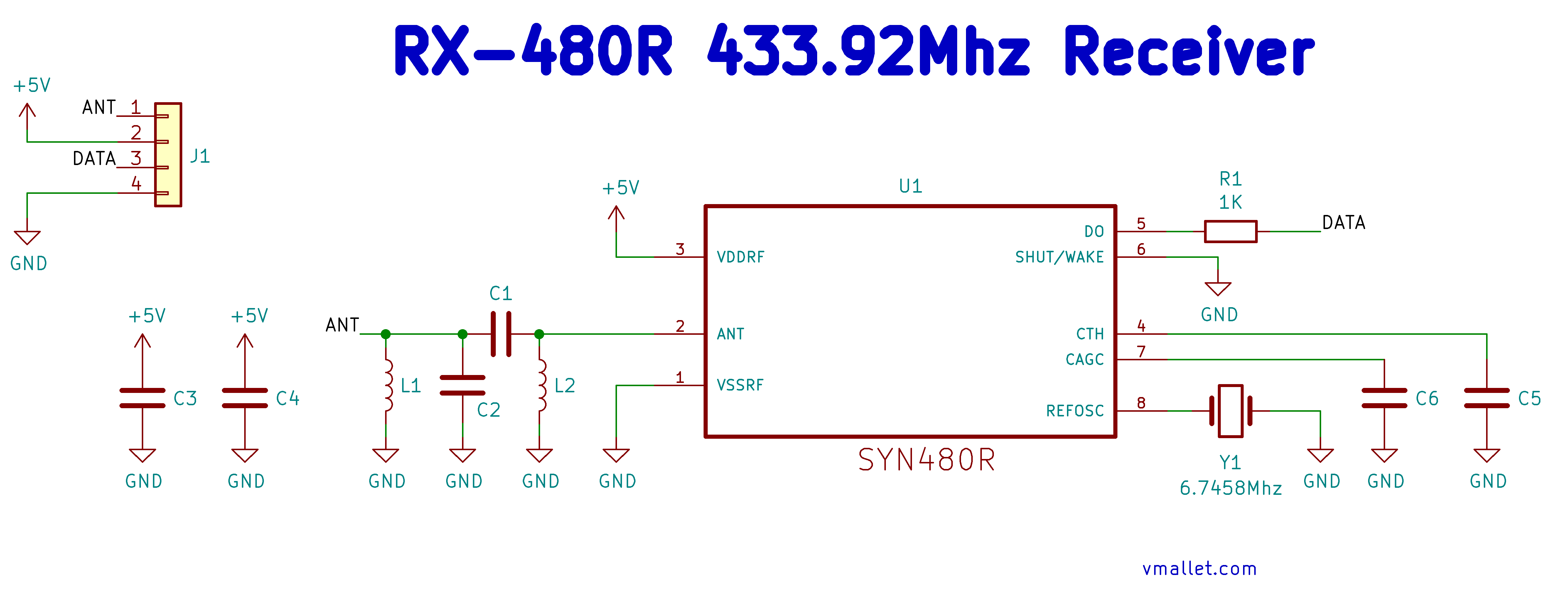
Not too much to write about here, this is pretty much the same as the reference design they have in the SYN480R datasheet.
Teardown: Remote
The remote is simple and light. It can control four plugs either individually or all at once.
Inside the 23A battery tray are two little screws. With the screws removed everything comes apart nicely.
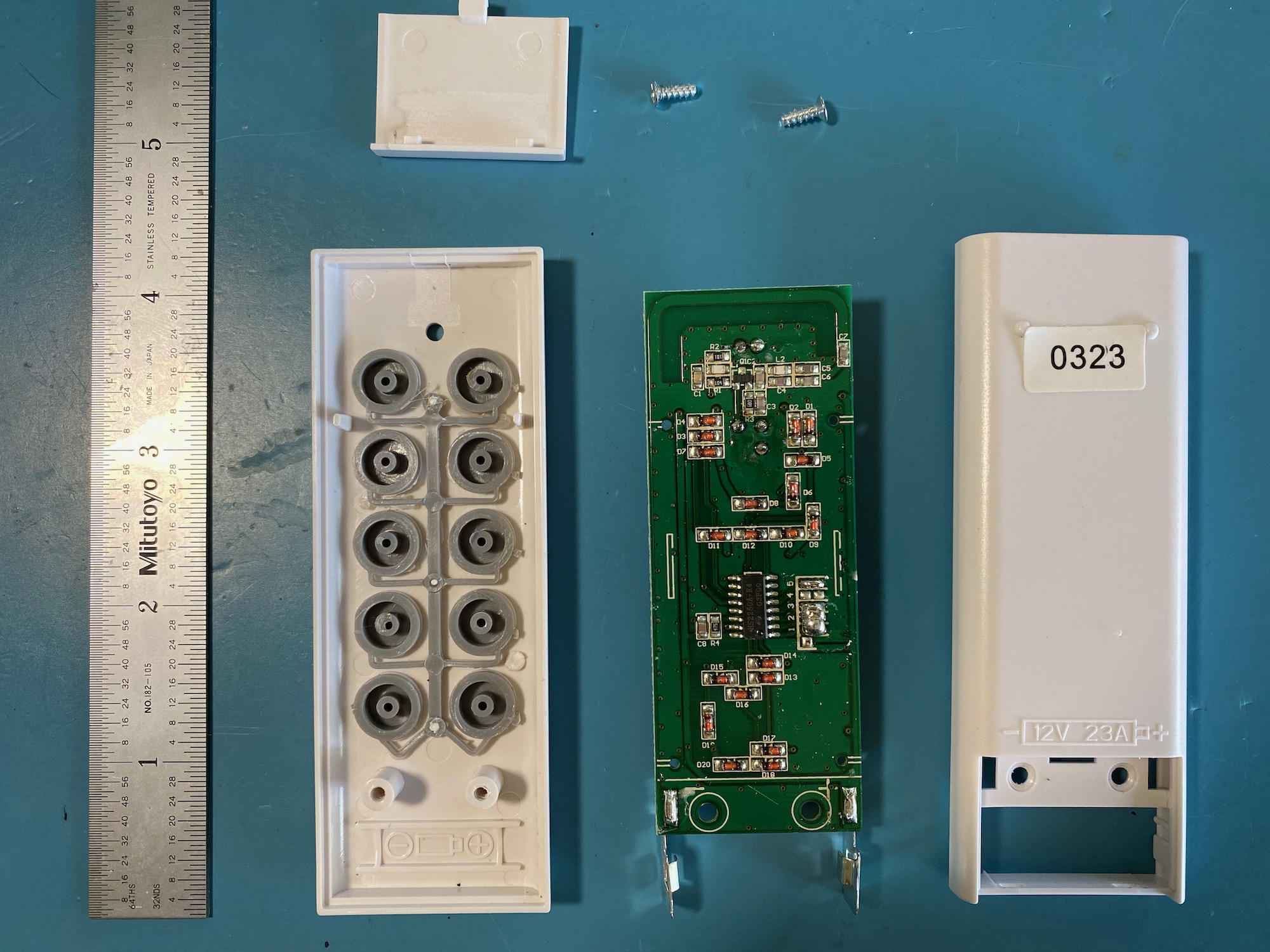
What we care most about is the circuit, let’s take a closer look:
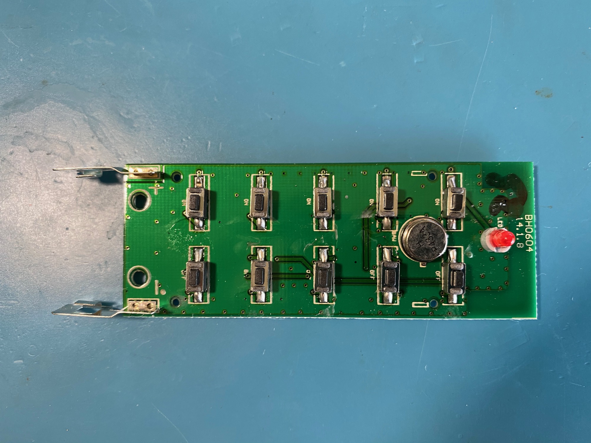
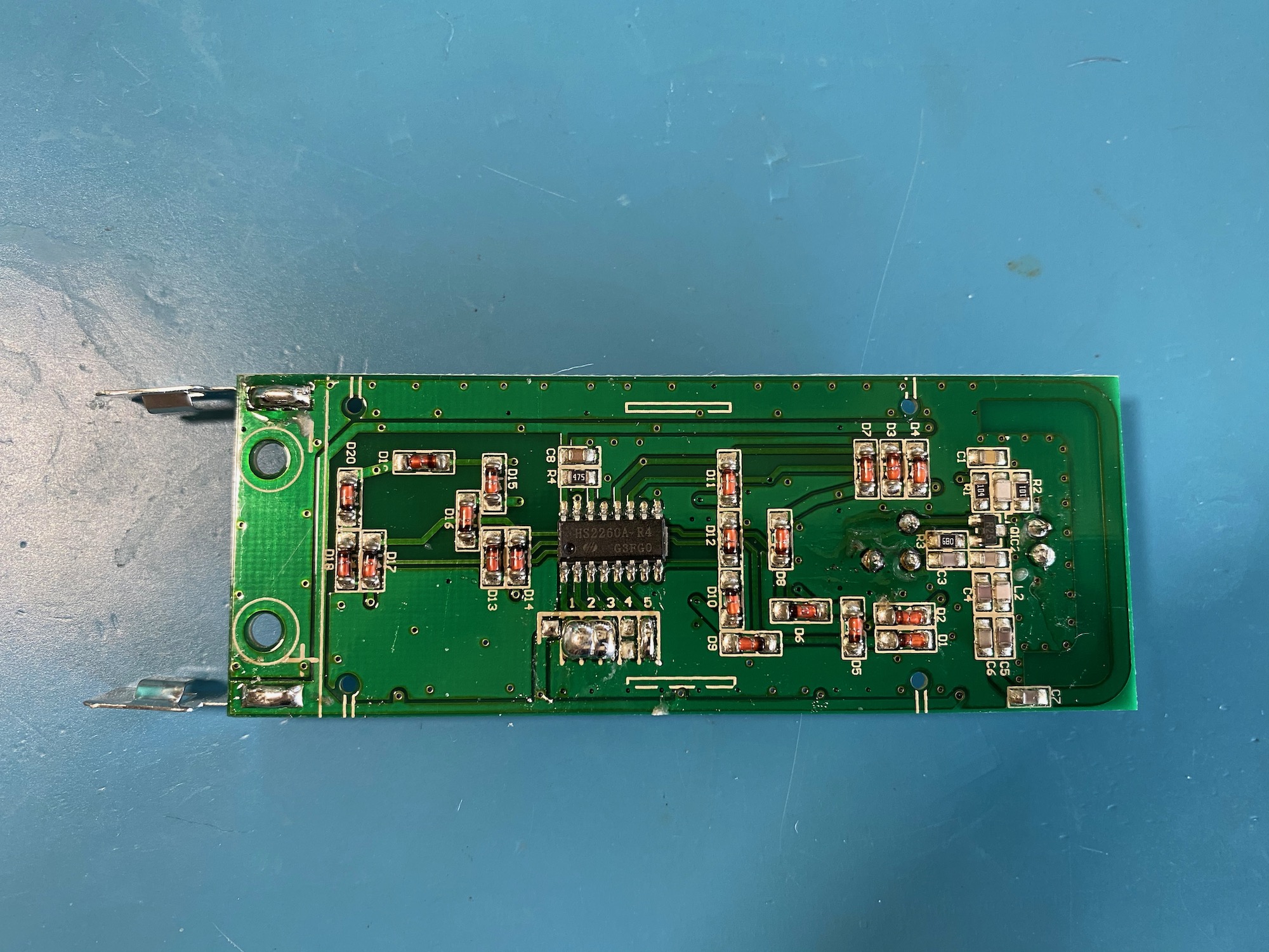
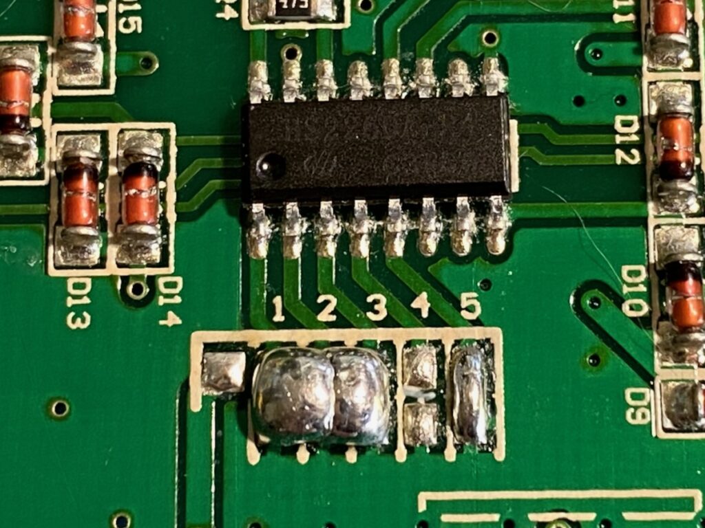
The remote’s PCB has 10 physical push-buttons on one side along with a 433.92Mhz SAW resonator and an LED, and the other side has the main HS2260A-R4 encoding chip with a bunch of passives, and a trace antenna.
Remote’s circuit analysis
The main (and only) chip is a HuaXin HS2260A-R4 Remote Control Encoder. There are 20 diodes, a bunch of passives, one transistor, and a resonator. How does it all work?
The HS2260A datasheet is not very helpful (it being in pretty light, and all in Chinese..) but with a bit of magic translation fu we see it is compatible with another part, Princeton Technology PT2260 Remote Control Encoder (PDF) and that datasheet is a bit more helpful. (I wish I had known that before tackling the Protocol section further on; live and learn).
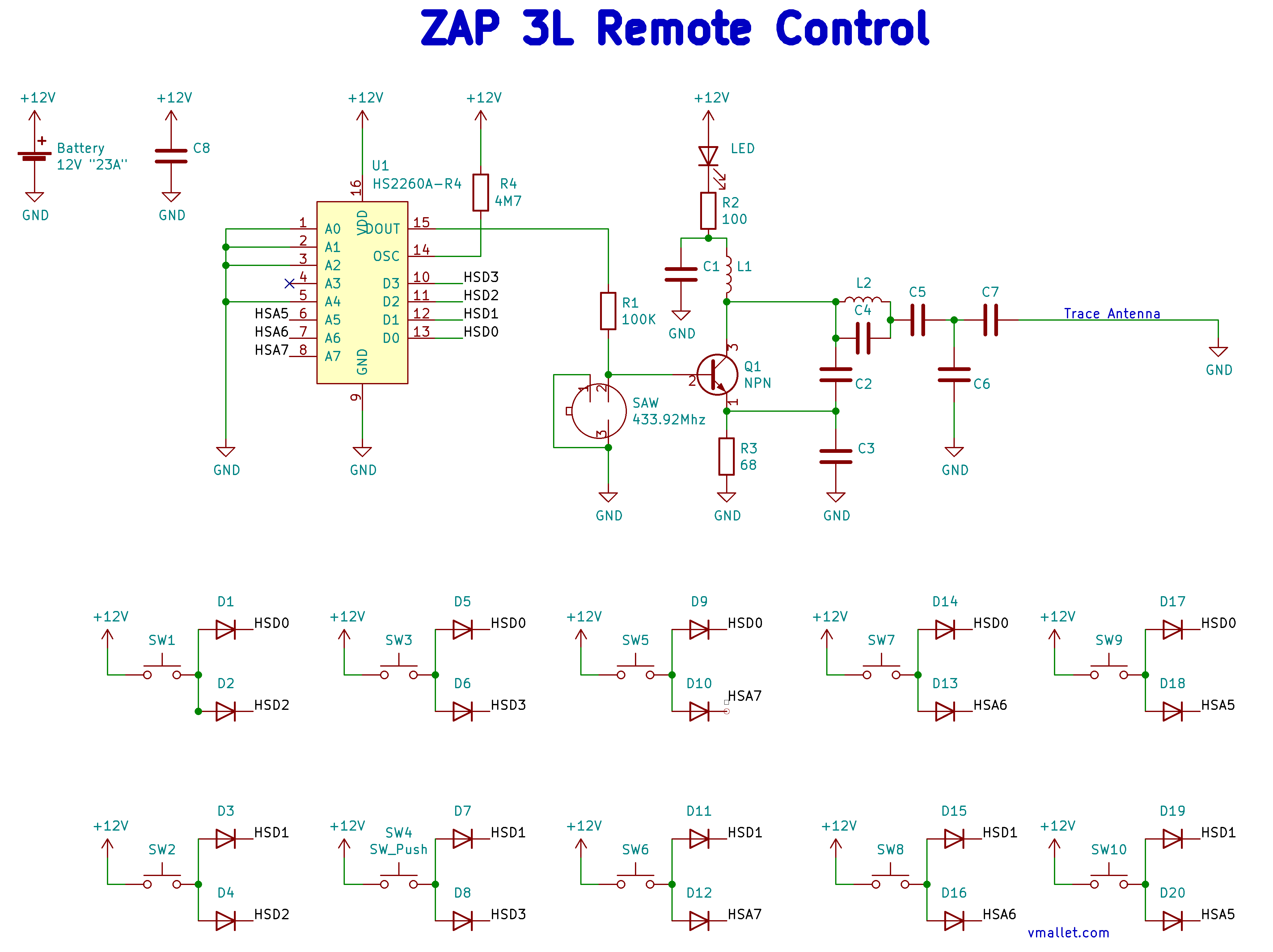
The first thing to notice is that there is absolutely no power regulation going on here; the battery directly feeds 12V to the chip with just one bypass capacitor (C8). I don’t know if the chip could survive having the battery reversed and there is nothing in the battery holder to prevent it from happening. Hmm..
The encoder
The chip as 8 address lines A0->A7 and 4 data pins, D0->D3. The chip is always powered on and goes straight to idle mode, consuming almost no power. As soon as the chip notices one of the 4 data pins going high, it starts pulsing its encoded data on its DOUT pin. By doing so it activates the transmitter section which pushes power through the antenna. In this application, the chip has 5 of its 8 address lines (A0->A4) used for the pre-configured “channel” and three address lines (A5, A6, A7) used as data.
Each button is tied to +12V on one side and to two of the 7 data pins (D0->D3, A5->A7) through a bunch of protection diodes. 5 of the pins are to indicate which plug to act on (1, 2, 3, 4, or ALL), and two of the pins are to convey the ON (D0) or OFF (D1) state.
The transmitter
The 433.92Mhz transmitter is a bit beyond my understanding here, but it seems to be of a reasonably common design. Its three main components are the Surface-Acoustic-Wave (SAW) resonator (similar to this one: RFM RO3101 (pdf)), an RF transistor (markings “R25”, possibly a Renesas 2SC3356 (pdf)), and a trace antenna. Pulses on the DOUT pin of the main chip will drive the RF transistor to in turn drive 433.92Mhz pulses out for the receiver to retrieve on the other end.
A look at the protocol
I spent some time looking at the encoded signal coming out of the DOUT pin of the encoding chip to figure out the protocol used between the remote and the plugs and it’s only once it all made sense that I discovered the PT2260 datasheet which explains a good part of it… Anyways, let’s take a look 🙂
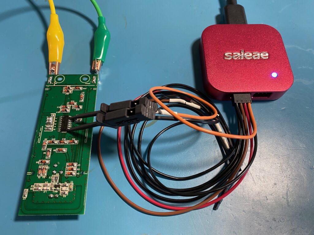
I plugged the Saleae Logic Pro 8 logic analyzer onto the DOUT pin (Pin 15) and recorded a button press. DOUT is conveniently kept at 0V when idle so any activity on DOUT would be very visible. DOUT swings between 0V and 12V and luckily the Logic Pro’s inputs can tolerate the 12V high so we are in business.
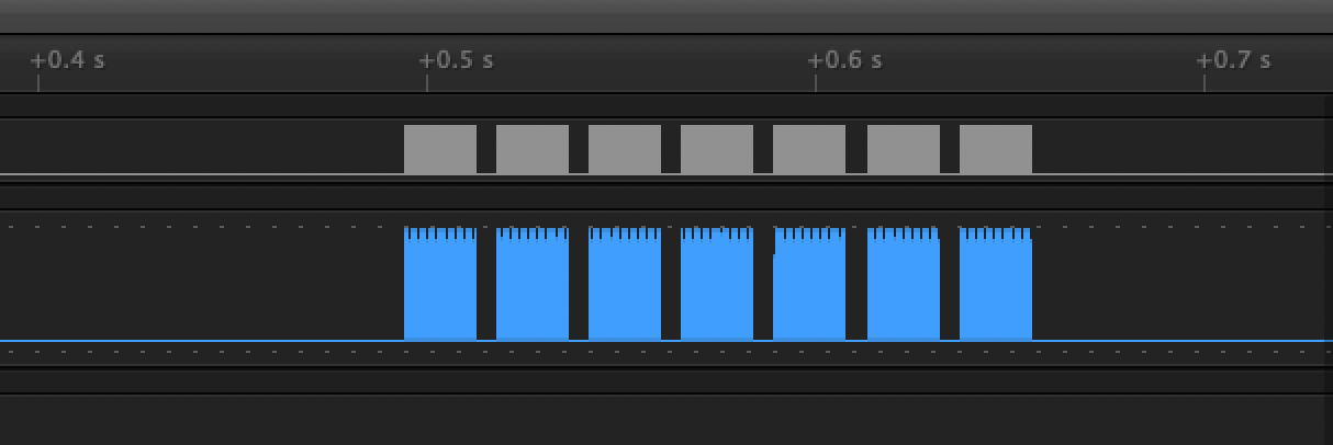
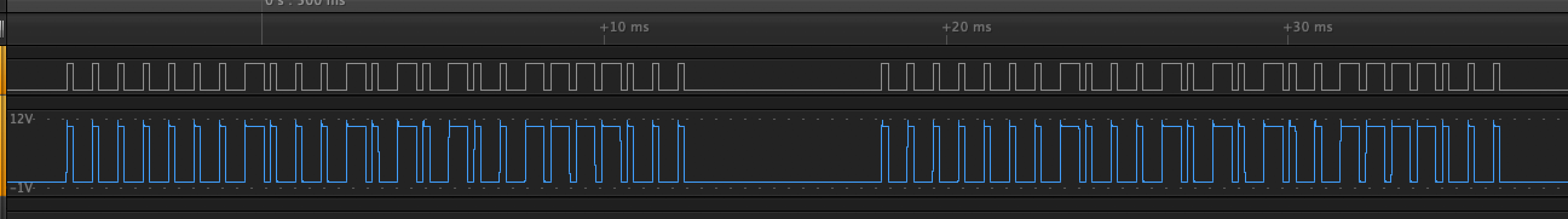
Ok that looks promising. One short button press (“click!”) on the remote resulted in 7 bursts of activity on DOUT. Zooming in a bit and we see something we might be able to work with: regular pulses, long and short, in repeating bursts.
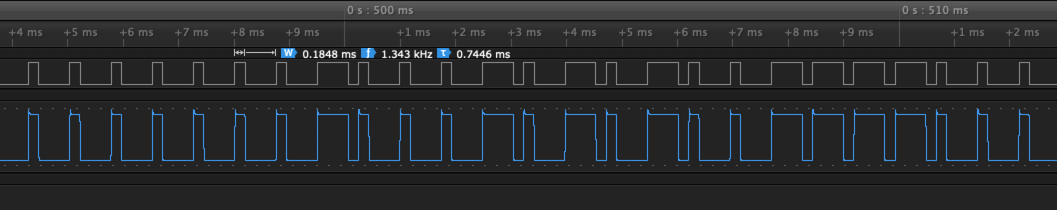
By counting the short pulses as 0s and long pulses as 1s (and ignoring the last bit which might be a stop pulse of sorts), we can get a useful representation of the burst. For this example we get:
0000 0001 0001 0101 0011 1100 (Button 2, “1 OFF”)
After analyzing the data for the 10 buttons, clear patterns started to emerge as to which input line affected which parts of the 24 bits. And after discovering the datasheet for the PT2260 compatible chip, it became even clearer…
The 24 bits represent the state of the 12 input pins, 2 bits per pin to support the address pins that can have three states (High, Low, or left floating). The D0 through D3 data pins are either High or Low, and have internal pull-downs to make them Low if they are left floating.
- 0 -> “00”
- 1 -> “11”
- floating -> “01”
The 12 pins are transmitted in order, as such:
A0 A1 A2 A3 A4 A5 A6 A7 D0 D1 D2 D3
For example when we press Button 2 “1 OFF” which uses D1 and D2, the remote sends:
- Pre-configured address A0 -> A4 (0, 0, 0, F, 0) -> 00 00 00 01 00
- A5, A6, A7 left floating: F, F, F -> 01 01 01
- D0 Low (floating), D1 High, D2 High, D3 Low (floating) -> 00 11 11 00
- => 0000 0001 0001 0101 0011 1100
Here’s a recap of lines go High when a given button is pressed based on our schematics:
| A5 | A6 | A7 | D0 | D1 | D2 | D3 | |
| 1 ON | H | H | |||||
| 1 OFF | H | H | |||||
| 2 ON | H | H | |||||
| 2 OFF | H | H | |||||
| 3 ON | H | H | |||||
| 3 OFF | H | H | |||||
| 4 ON | H | H | |||||
| 4 OFF | H | H | |||||
| ALL ON | H | H | |||||
| ALL OFF | H | H |
When a button is pressed the remote sends to pieces of information: which plug to act on (1 through 4, or ALL) and whether to turn these ON or OFF. Each of the 7 input pins maps to a specific bit of information:
- A5: ALL outlets
- A6: Outlet 4
- A7: Outlet 3
- D0: TURN ON
- D1: TURN OFF
- D2: Outlet 1
- D3: Outlet 2
Lastly, the datasheet tells us the HS2260A will start transmitting as soon as it sees a High on one of the four data pins. When that happens it starts sending the 24 bits for the 12 states and waits for a short time (about 5ms in our case). If when it’s done waiting one of the data pins is still High, it will start sending the whole 24 bits again. Hence why we see many bursts for a single button press; and if we kept the button pressed it would keep sending the same sequence over and over again.
Security: is there any? (aka: Can my neighbors control my plugs?)
Security? Not really. There is no authentication, no encryption of any kind, just a straight up blasting of bits in the air and receiving on the other end. The only thing that is in place is the matching pre-configured “channels” in the remote and the outlets.
These devices are pretty simple and have a fixed “channel” (address) that is set at the factory and it is clearly not intended for a consumer to be able to change it.
The chip has 8 address lines that can have three states (High, Low, Floating) so in theory we could have 3^8 (i.e. 59,059) different addresses. Not too bad…
… but here, two things. They use 3 address lines for data so that leaves us with 5 usable ones for actual addresses; and the way they configure these 5 address lines appears to just be by pulling them to GND or by leaving them floating. That’s only 2 states, so now we have 2^5 = 32 addresses.
So it sounds like if both you and your neighbor buy these plugs you have a 1 in 32 chance of controlling each other’s plugs. Not ideal!
Appendix: testing the plug safely
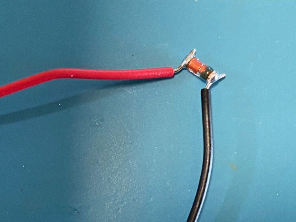
Because of the use of a Transfomerless Power Supply design described earlier testing and probing the circuit while the plug is connected to mains voltage is a really bad idea. But luckily now that we understand the circuit a bit better we know where to inject some safe DC voltage to allow us to work on the plug.
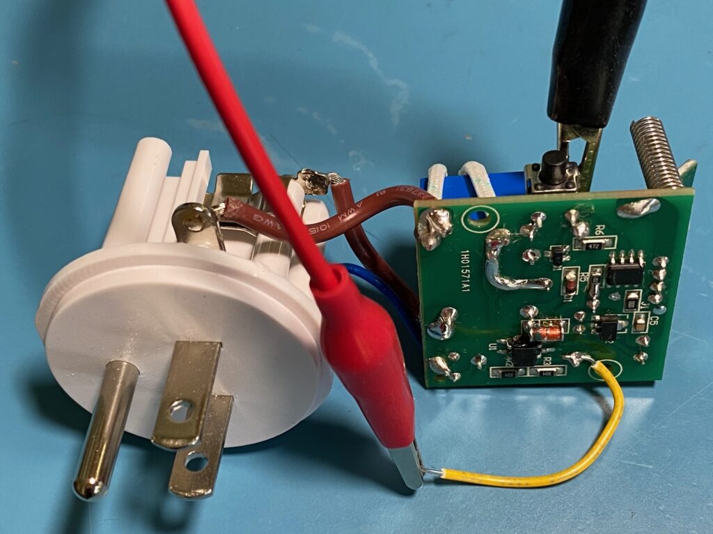
I chose to solder a wire to one of the pins of the big C1 capacitor, the pin that’s otherwise connected to the rectifier bridge. By connecting my bench power supply’s positive terminal to this wire and its negative terminal to the circuit’s ground (here using the conveniently accessible body of the push button) we inject about 24V DC right before the bridge. After dropping over one of the bridge’s diodes the current is ready to be used for the relay coil and the 5V regulator. It works beautifully and it makes it safe to look at signals and measure voltages.
Excellent tear down article! Very useful for me trying to figure out what’s going on with one of the 5 outlet not working
Good morning,
Can you Buy the RX-480 PCB from entree?
Regards
Anthony
Can You write value L1, L2 and capasitors C1-C7, on remonte control diagram, please?
I would have to desolder them to be able to measure them off-circuit but I can’t seem to be able to find the remote at the moment! It is somewhere I know, but where…
Found it! Took C1-C7 and L1, L2 out and measured them with my DE-5000 LCR meter. Not sure how valid these measurements are but here they are:
C1: 11nF — C2: 3.8pF — C3: 8.6pF — C4: 1.2pF — C5: 21pF — C6: 0.9pF — C7: 0.9pF
L1: 1.2mH @1KHz — L2: 4mH @1KHz
I know – Q1 is R25 -> so, 2SC3356 NEC NPN transistor
Hi your measurments aren’t correct.
“L1: 1.2mH @1KHz — L2: 4mH @1KHz”
I worked for company that makes simple pilot things. The values are in the range of 1nH to hundreds of nHs. These are chip inductors in 0805 case. There are also wirewound 0805 ones with much greater “q” factor.
All measurments for that low values should be done in hundreds kiloHertz. Just try to search something like “RF chip inductor application note”
Tiny correction but F1, the thermal cut off fuse is 115°C not 115°F
I have been using these switches for years, just recently one stopped working and I opened it up, determined the thermal fuse had blown. In my case, they used a different brand, (https://setsafe.com/SdwlUploads/set/ATCO%20S(Radial%20)_SETsafe%20&%20SETfuse.pdf ) product model S115
Now I need to consider whether it’s worth purchasing a replacement fuse and repairing it, or not.