Today’s teardown is about the Gosund WP3 smart plug. It is cheap, popular, and modern, and I wanted to look at the circuit and build schematics for it so here we go. It will be interesting to see the difference with the ZAP 3L Remote Control outlet from the last teardown.
The Device
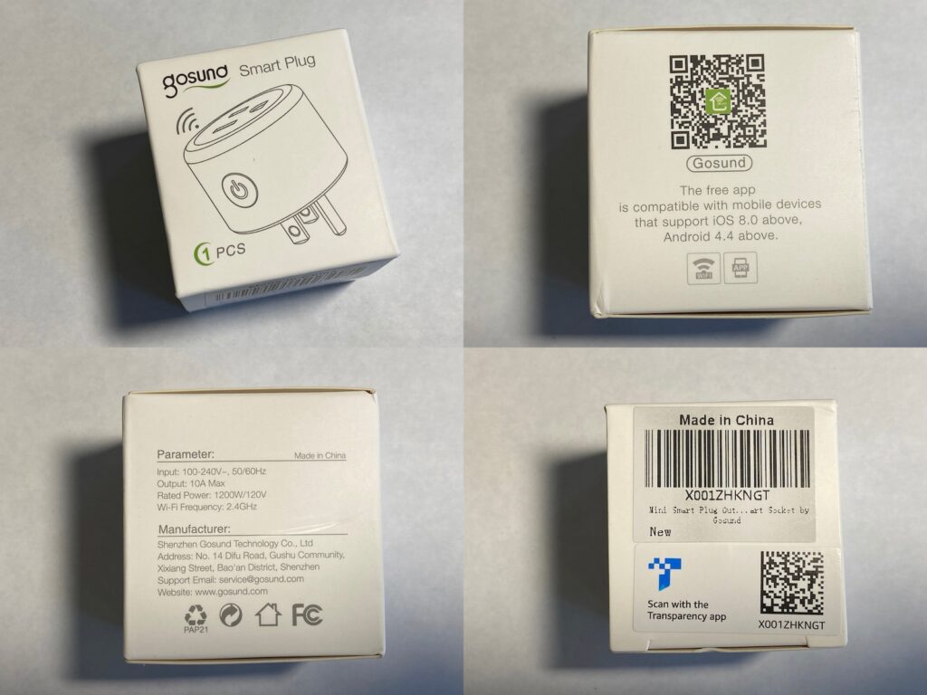
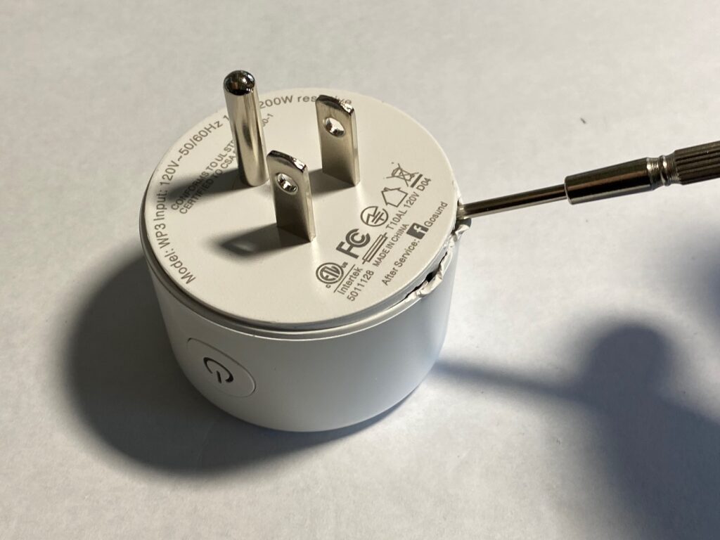
This is the Gosund WP3 Smart Plug (gosund.com), a plug that lets you control an appliance via WiFi or your home assistant (Amazon Alexa or Google Home, no Siri). It is a very compact device and it is remarkably cheap, too: as of today you can find it on Amazon US for $6.99, or $20.39 for a pack of four.
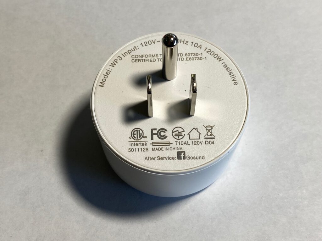
The plug has a nice and very solid feel in hand, and there is not a hint of play in the case or the prongs. It weighs 51g (1.8oz) and measures 30.3mm (1.19″) (height without the prongs) by 50mm (1.94″) (diameter). The body has a very slight taper towards the top: 50mm diameter at the bottom vs 48.8mm (1.92″) at the top. Sadly it is not possible to put a plug on each of the two outlets of a standard American outlet because it is not narrow enough.
The specs:
- 100-240V, 50/60Hz
- 10A max load
- Rated power: 1200W/120V
- WiFi Frequency: 2.4Ghz
- Compatible with iOS and Android
- Works with Amazon Alexa and Google Home
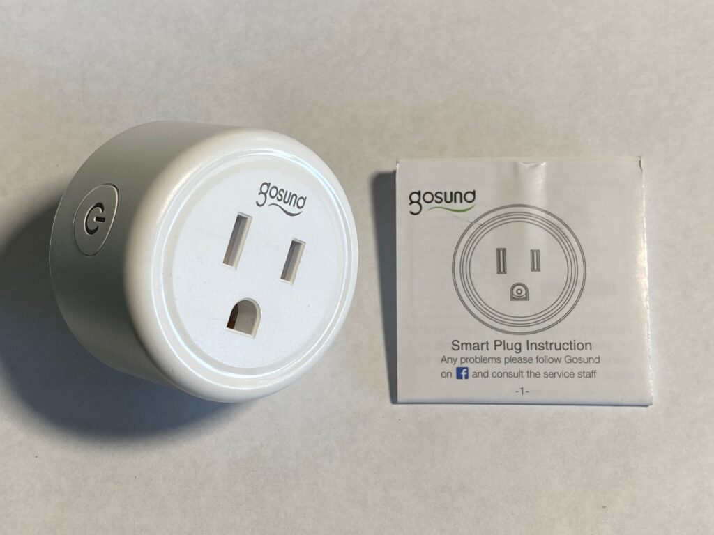
My unit came in a tiny box barely bigger than the device itself. Inside is the plug with a cover on the prongs, and a tiny manual.
The plug has a single button on the side that can light up to indicate various states.
Teardown
Warning: this device uses a non-isolated power supply design which can be lethal or extremely dangerous when its internals are exposed. Gosund did a good job at making it completely enclosed and sealed (and thus very safe), but if you open it you expose yourself to the circuit and *any* part of the circuit could kill you, even those labeled “3.3V”. Do NOT connect this plug to the wall if it is open. If you want to play with it, check out the section “Testing the device safely” at the end.
Cracking this baby open without damaging the case is not trivial. There are no screws, it is a press-fit design that has been glued to prevent it from coming apart. This exploded view on Gosund’s page gives you a clearer idea of what to expect inside. I had reasonable success inserting a screwdriver in the seam at the base of the plug and running it all along the edge to try to break the glued seal, and then popping off the base.
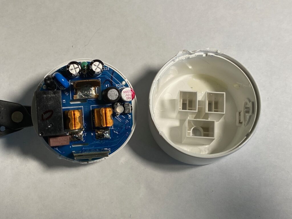
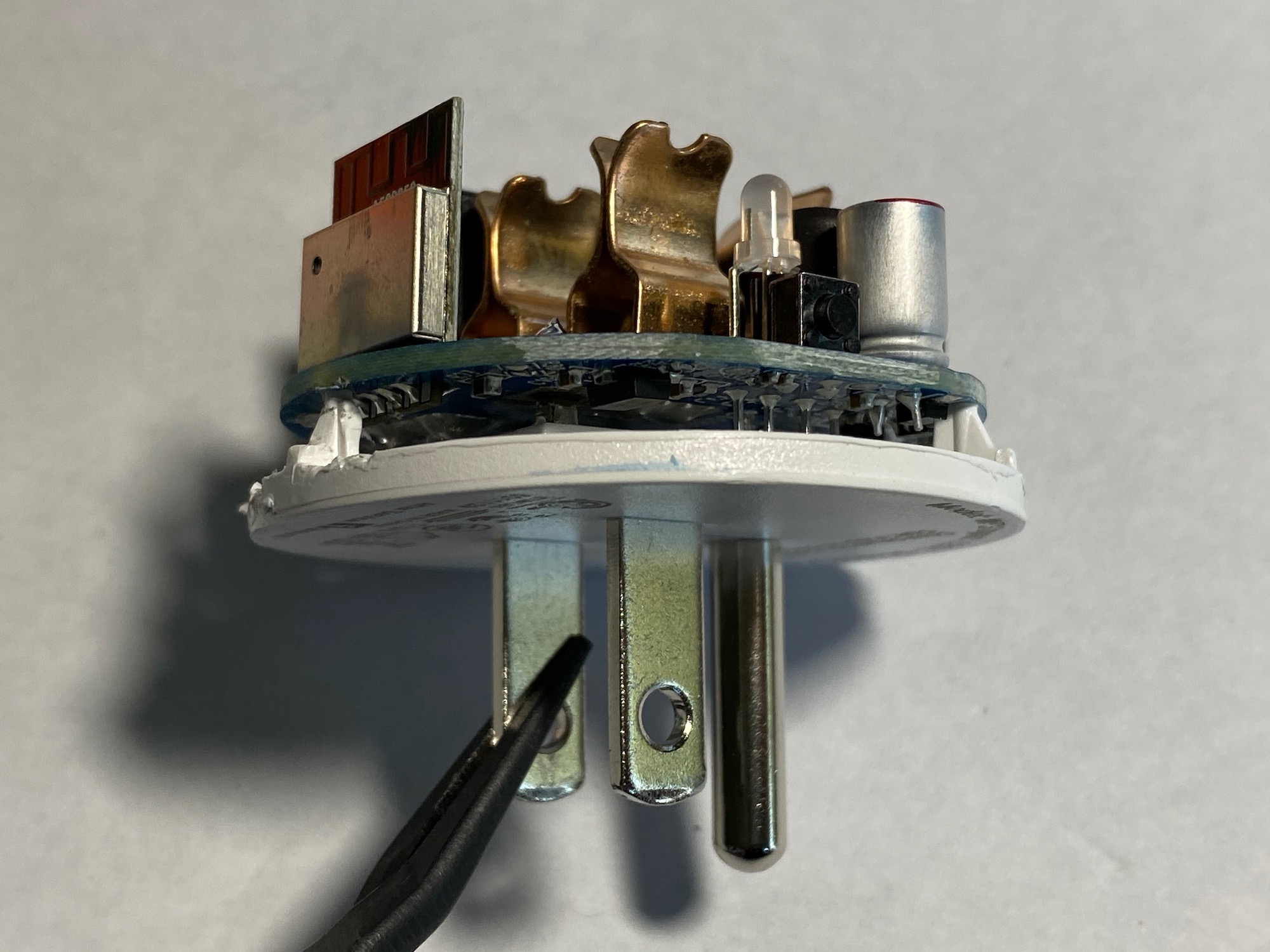
The PCB is soldered to the prongs which are not moving away from the bottom part of the case, so we will have to desolder the prongs to get access to the underside of the PCB.
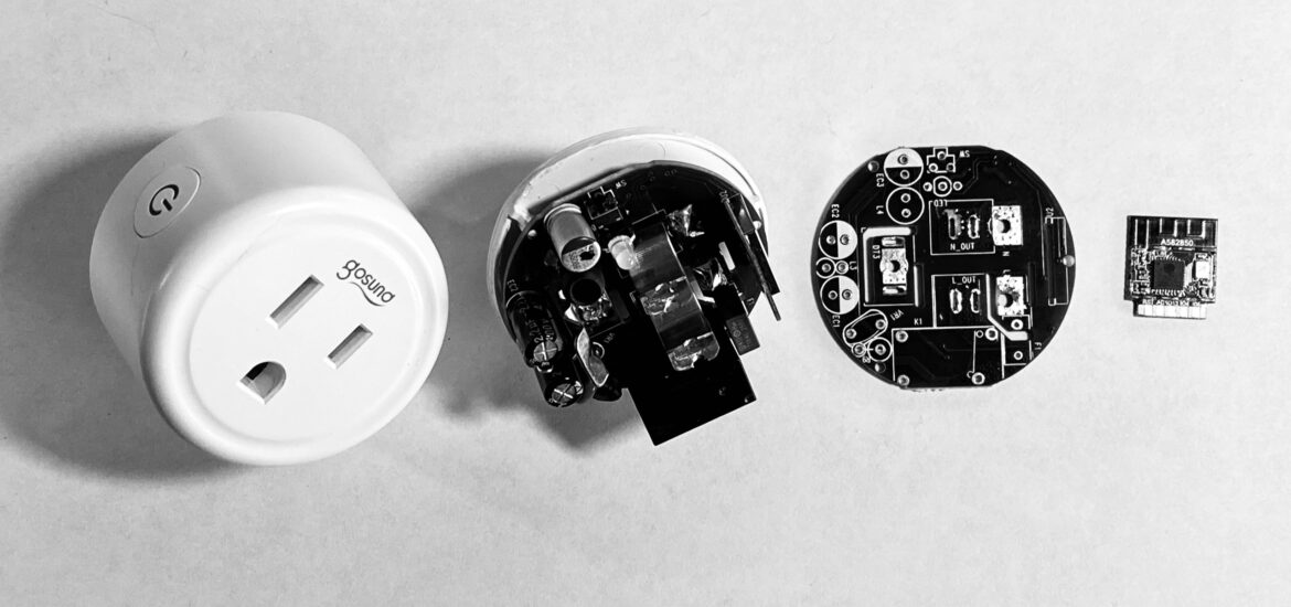
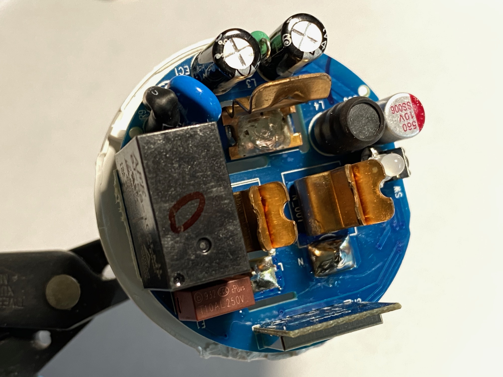
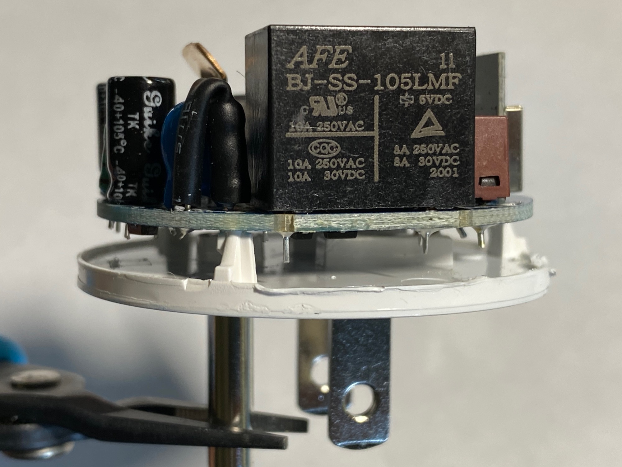
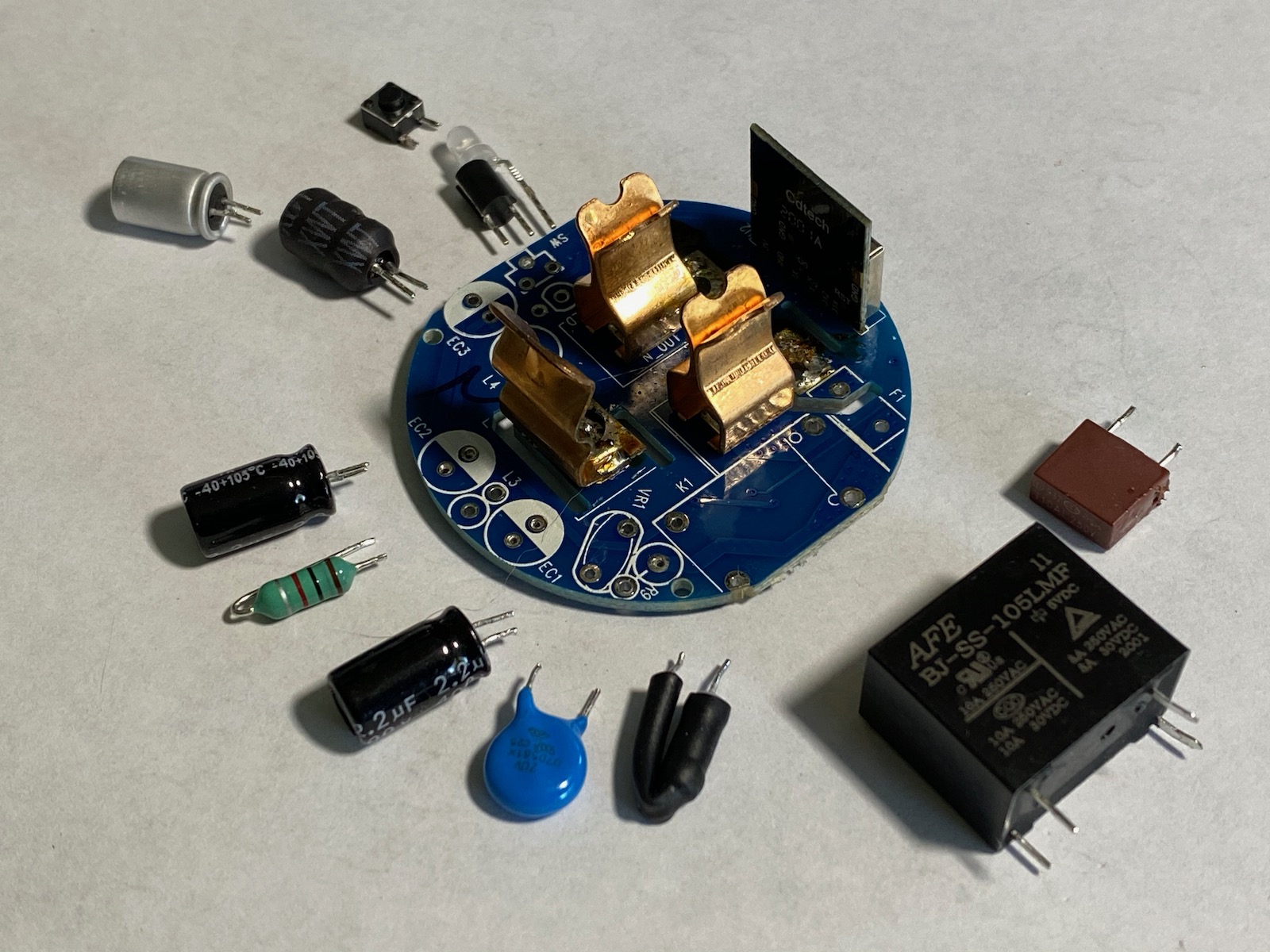
The top of the PCB has the usual suspects: the female mains terminals, the main relay, capacitors / inductors for the power supply, the tactile switch and the status LED, and the tiny WiFi control module. No transformer here so we have another non-isolated, transformerless power supply!
A lot of solder wick later the PCB came loose from its prongs. I had decided to sacrifice this plug and didn’t take too much care while desoldering the prongs and I ripped the through-hole plating. There are better ways to do this but it got the job done..
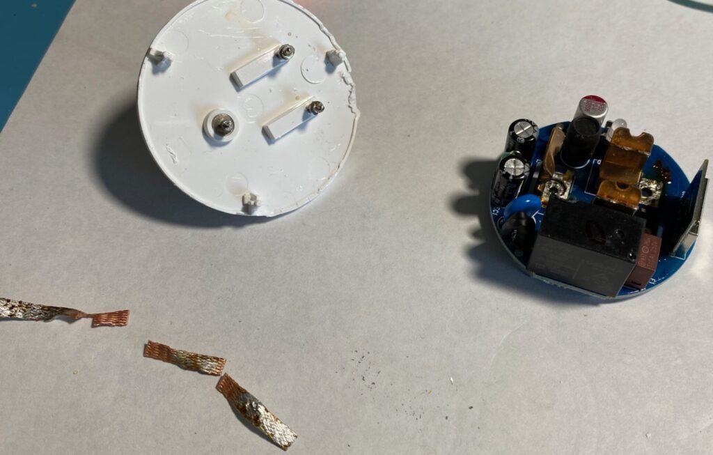
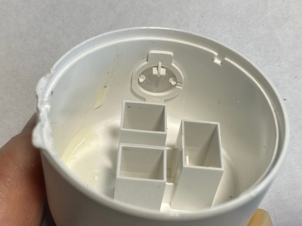
Now we see why the prongs don’t budge at all in the plug: they are trapped in the base plastic molding. It is good from a safety standpoint too, there is no way these prongs will come out of the plug even if someone is very motivated.
PCB: a closer look
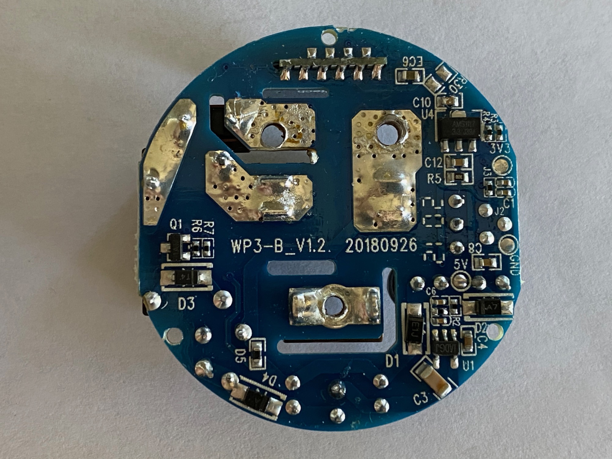
The PCB is a 2-layer PCB with all the through-hole components on top and all the SMD components on the bottom. The markings on it are:
- WP3-B_V1.2
- 20180926
- 21 02
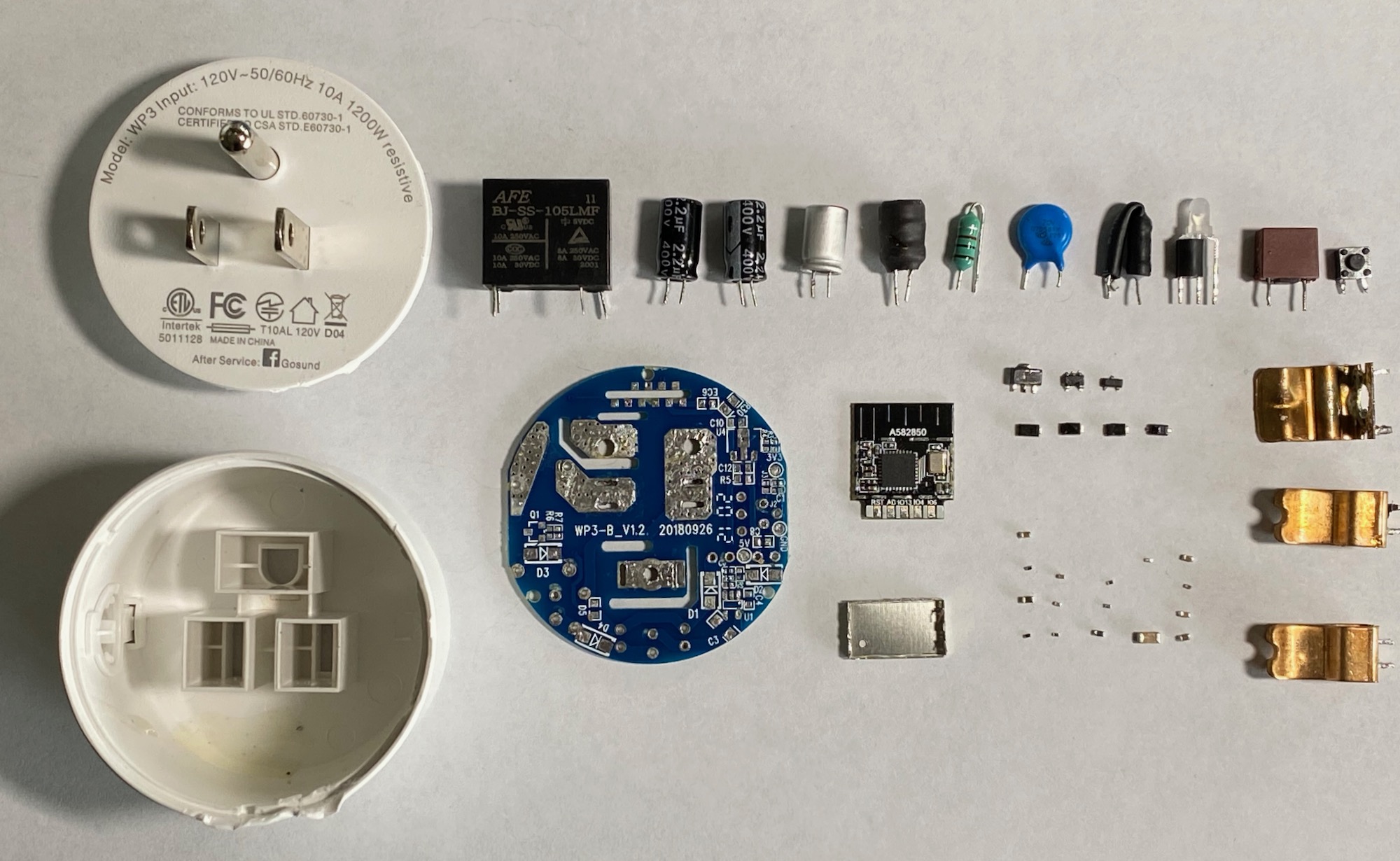
In order to draw the schematic of the circuit I proceeded to remove all components so I could measure them out-of-circuit.
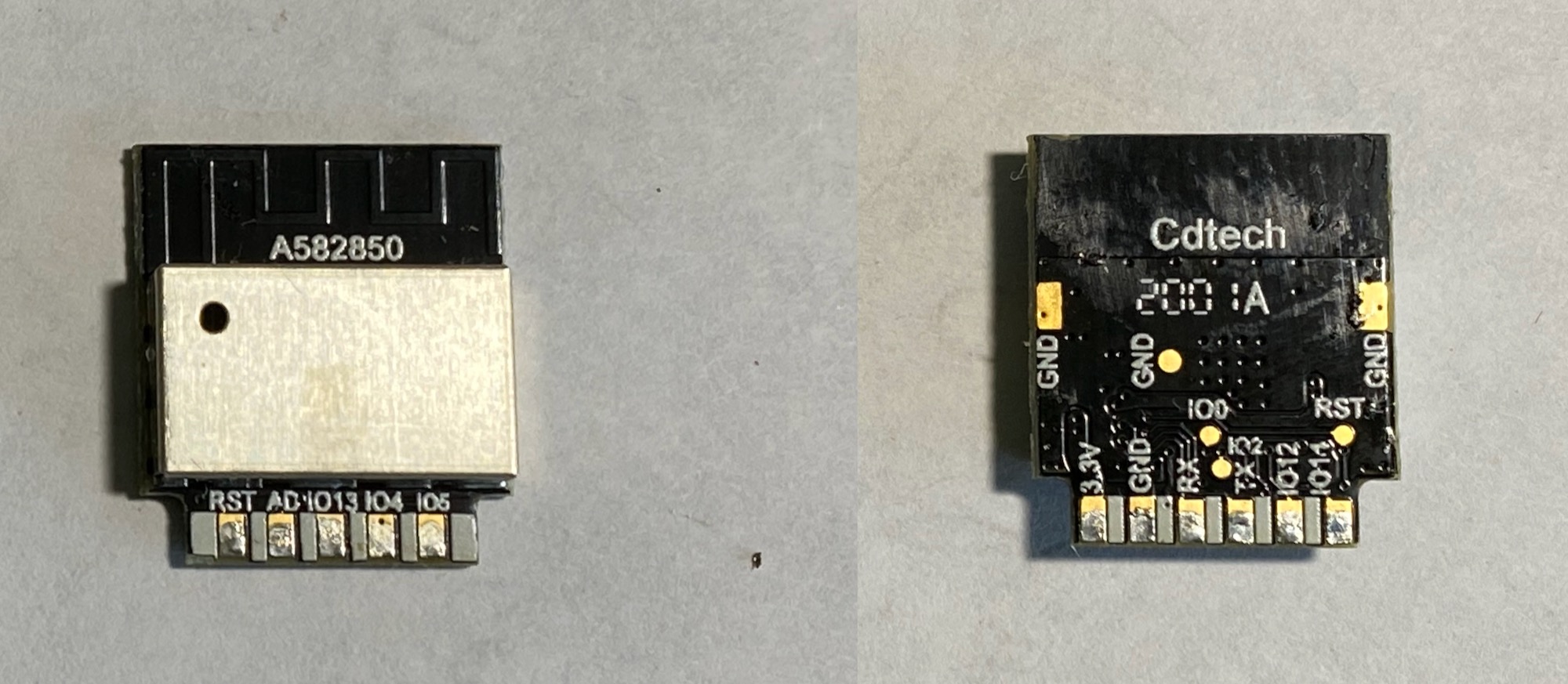
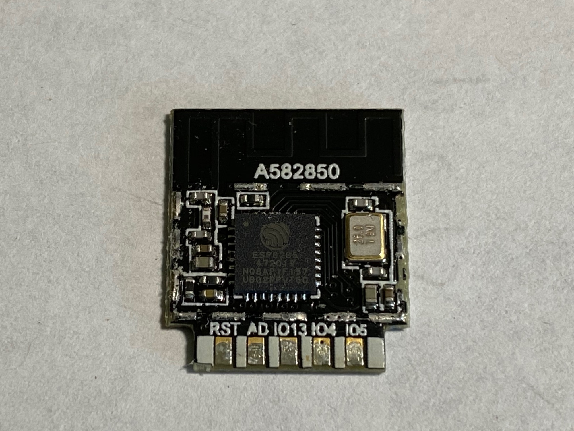
The brains of the smart plug is an Espressif ESP8285 WiFi SoC (datasheet PDF) which is pretty much the same as the ever popular ESP8266 bundled with 1MB of internal flash. It’s a QFN-32 package sitting on a tiny PCB made by Cdtech and hiding behind an EMI shield. This thing is highly reprogrammable, see further down for some pointers.
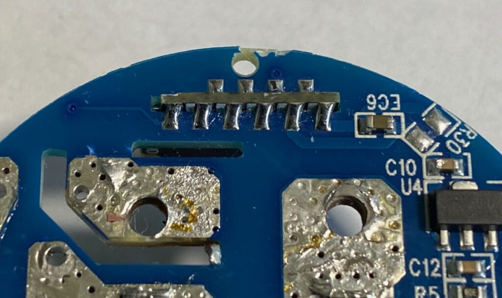
The Cdtech module has pads on both sides of the bottom edge of its PCB and is mounted by inserting this edge into a slot of the main PCB and soldering directly to these pads. Here’s a close-up of the connection seen from the underside of the main PCB.
And this is what the plug looks like when everything is taken apart…
The Schematic
After spending some time with my meters and some good magnifiers here’s the schematic I came up with:
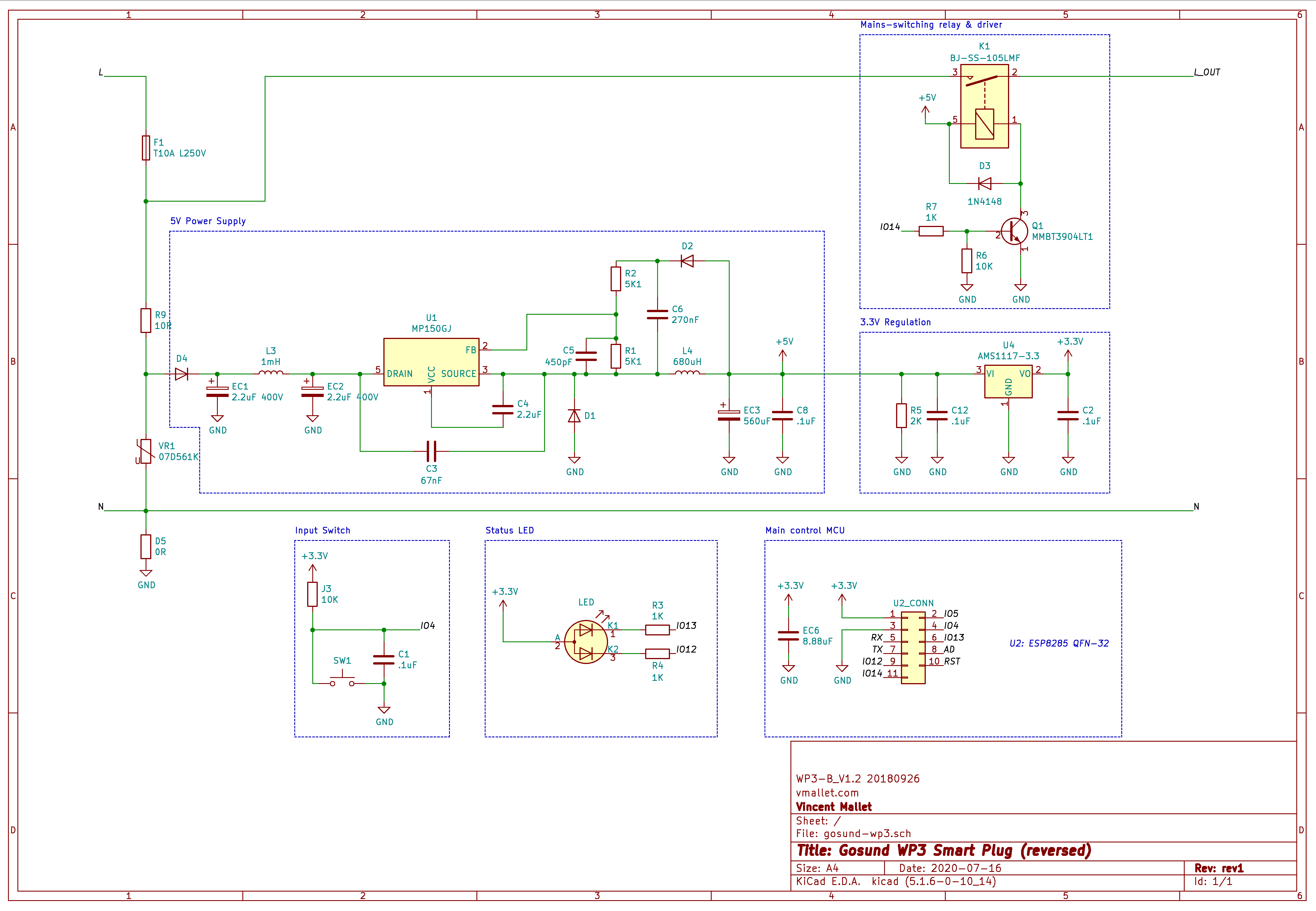
I see six sections plus a couple of protection components:
- Main 5V power supply
- 3.3V power supply
- The main MCU board
- Input: push button
- UI: LED
- Relay & driving circuitry
5V Power Supply
The 5V power supply is a non-isolated transformerless power supply (which means: do not ever touch any part of this circuit board ever when it’s plugged into the wall, not with your hands, not with a FTDI chip, not with a programmer, just don’t!).
It is built around the MPS MP150 Offline primary side regulator (datasheet PDF) which does the heavy lifting. The design used here is pretty much the same as the reference design suggested by MPS in the linked datasheet save for a missing diode (“D4” in the datasheet) and a couple of different values. It takes in anything from 100V to 240V AC and produces a stable 5V DC at its output.
3.3V Power Supply
This one is really straightfoward, using a pretty common 3.3V LDO regulator (AMS1117 pdf) to drop from 5V to 3V3
Main MCU Board
This is the Cdtech module with the Espressif ESP8285 SoC, see the previous section for more information and the datasheet.
Input Switch
The input switch drives the GPIO4 line of the MCU. GPIO4 is pulled up with a 10K resistor (labeled “J3” instead of “Rxx” on the PCB) and pressing the switch will tie GPIO4 to GND. C1 is here for a bit of debouncing.
Status LED
The LED is a bi-color red/blue LED with common anode. It is driven by lines GPIO12 and GPIO13 of the MCU.
Relay and Driver
The heavy-lifter of the plug is the BJ-SS-105LMF Relay which can switch up to 10A at 250V. The relay’s coil nominal voltage is 5V which comes from the 5V PSU above.
One leg of the coil is tied to 5V, the other is driven by the Q1 NPN transistor which pulls it to GND when activated. Q1’s gate is pulled down to GND by R6 and is connected to GPIO14 of the MCU through a 1K limiting resistor R7.
The case of D5 “diode”
Usually when a component is labeled “D5” you can expect it is a diode of sorts. When I started looking at it more closely I started being surprised: the component has no visible marking that would let one know the direction of the diode. The PCB silkscreen around D5 also shows no indication of direction (unlike the other 4 diodes). After measuring D5 it appeared to simply be jumper (i.e. a 0 Ohm resistor). I asked on the EEVBlog forum and folks confirmed my suspicion. Someone must have initially included D5 when copying the MPS reference design, and someone else must have later axed it by replacing it with a jumper but without changing its label. Ha!
Bits of protection
- F1 is a slow-blow, 10A 250V fuse that will cut power to the whole plug (including the control circuit) if 10A is exceeded for too long.
- R9 is a 10 Ohm resistor to limit the inrush current when the plug is first connected and the capacitors start charging with a high current.
- VR1 is a 07D561K varistor (example datasheet, this one is not a Bourns though) that will shunt voltage spikes to protect the circuit
Other teardowns and hackability
There is at least one other teardown out there for this plug, the Gosund Smart Socket Teardown by FixitFrank (youtube).
What is interesting with this plug is that it is driven by a pretty common chip as you saw above (the ESP8285) and some folks have made it easy to re-flash it with your own firmware.
Two projects are of interest:
- Tasmota (tasmota on GitHub): an open source firmware for ESP8266 devices. There are so many smart things out there that run on an ESP8266 (or derivative) that can get this fancy firmware, it is very cool.
- Tuya-Convert (GitHub): “A collection of scripts to flash Tuya IoT devices to alternative firmwares”. It turns out the Gosund WP3 outlet is made by a Chinese company named Tuya (which makes all kinds of solutions for other companies to re-brand). Some folks at vtrust.de and c’t magazine put together this tool that allows tuya (and hence gosund) devices to be flashed over-the-air which is good in this case given how destructive opening the outlet is. It is also a much safer approach to hacking the device 🙂
Testing the device safely
Hopefully by now you are convinced you should not plug this device into the wall if it is open even just to “try it out”, one little mistake and you could die..
Based on the design of the power supply feeding it a DC voltage high enough to let the MP150 do its job should enable us to test the circuit and play with the app, toggle the relay, etc.
For me the plug came to life with a 20VDC between the two prongs.
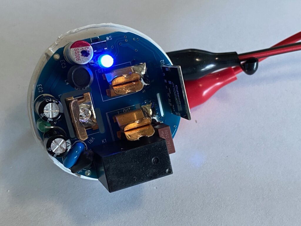
With a 20VDC voltage across the prongs it is now safe to play with, test and poke without risking our lives.
Thanks for this useful analysis!
I tried to use TuyaConvert on my Gosund WP3. I was able to update the firmware to tasmota.bin, but wasn’t able to access the
device’s Tasmota web page.
I took it apart, unsoldered the ESP8285 module, soldered pins to it, connected to an FTDI USB interface, and updated the firmware using Tasmotizer. I somehow managed to fry the transistor that controls the relay. This teardown and schematic
helped my replace it with a 3904 NPN.
Was there any obvious hardware revision info on the circuit board or did you note the claimed revision on the Gosund app before the conversion? I’ve got 3 rev. 1.03 and 1 rev 1.04 and trying to figure out if they can be converted without brutalizing the case.
This is really a top notch review, thanks for the effort.
Great teardown and analysis. This is very useful.
I just had one of these go bad. Stopped outputting main power. Still connects to the net and switches on and off well but just no power. It doesn’t even click now.
Fuse or relay maybe? I have opened it and see no damage or anomalies with my eyes.
If the fuse was bad nothing would get power so it would be pretty obvious. You say the MCU still gets power so that would tend to indicate the 5V/3V supply is good. I would start by probing the relay/driver block. If you ground pin 1 of the relay with a wire, does it click? If yes, then the relay is good. You could try to feed 3v3 to pin 11 of the little MCU board (aka “IO14”) to see if the relay clicks. If not, then the Q1 transistor is shot.
You could also measure the voltage at pin 11 (IO14) of the MCU board, you should get 0V when turned off and 3.3V when turned on, just to make sure. I wouldn’t imagine this being a problem unless the firmware got changed somehow, very unlikely.
Make sure you do all this only when powered via a low-voltage supply (as described at the end of this post), and NOT while plugged into the mains 🙂
Thanks much for that information Vincent. I pulled and tested the relay and it is very clickless. Gonna order a few of them. Try that.
Hi Vincent,
What is the purpose of the C3 capacitor that is between Drain and Source? I haven’t found it on the schematic given in the datasheet.
Update on my busted one… It’s still busted. Turns out the relay was/is good. When I tested it with my bench power supply I had it wired incorrectly (the PS that is). I did end up replacing the Q1 resister though. Still broke. Still connects. Just no clicks.
you’d probably fried the flash memory for the esp with bad power; it’d make for some lost hopes as things would seem to light up otherwise… even the ESP might respond over uart, or begin to do so!
Super cool!
Is it possible to flash the ESP without desoldering?
This is the most thorough teardown of any product that I’ve ever seen. Excellent work, Vincent!
Can I plug this on 220v? The box says 100-240v but the actual device says input:120v 😅
Thank you so much for the information. I had a couple of questions though, how is the MP150, powering up the ESP8285, when they state in the hardware design guidelines, a minimum of 500mA is needed. I have read that the ESP in general needs a burst of current at the beginning to turn on, so how MP150 is able to turn it on with only 200mA according to the datasheet.